Installing an EGO meter - photo essay
Posted: Sat Oct 07, 2006 12:12 am
i have been offline for a while as i moved house recently and so have been pretty damn busy as you can imagine. i also got the dreaded cold / flu that has been going around, so haven't been very productive. so anyway, finally got my internet connection on again at the new house today and thought i'd post a little about what i have been up to in the last 2 days.
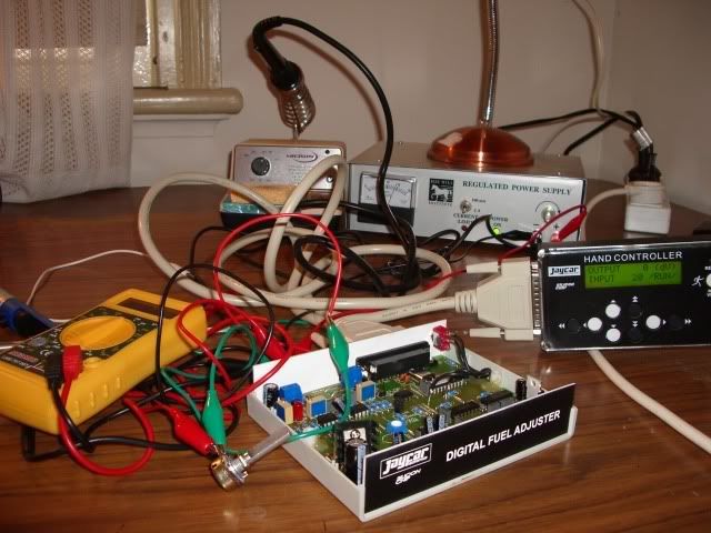
so i have been fiddling with this jaycar digital fuel adjuster (DFA) that i bought a few weeks ago. it's all finished and working perfectly on the test bench. this is a picture of the test / calibration rig. you can see the hand controller there in the picture as well, anyway it's all working as it should be
so before i install it in the car, i realised that unless i had some way to see what it was doing then it would be a waste of time. so i figured i'd need some way of monitoring the air/fuel mixture, via the O2 sensor, to see what affect any adjustments i make wiith the DFA are having. so of course my first port of call is to jaycar to see what kits they have. it turns out they have about 5 or 6 kits that all seem to do the same thing
i settled on the \"car fuel mixture display\" kit number KC5195, for $14.95, and here is the end result
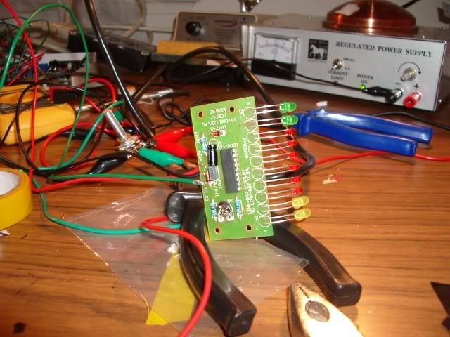
you'll notice that the red leds in the middle are 3mm leds while the yellow and green leds either side are 5mm leds. the kit comes with 5mm leds all round, using green ones in the middle and red ones at the lean end of the scale, and yellow at the rich end. i decided to set it up differently as i found the red leds aren't as bright as the yellow and green ones, so figured these would be best in the \"normal\" range rather than at the extreme of the scale. i aslo chose to use smaller leds in the red range, purely coz i thought it would look better / less instrusive.
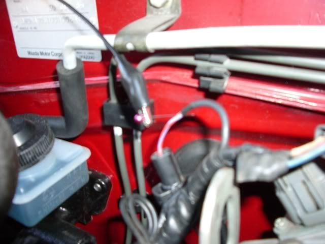
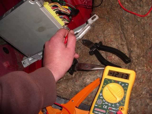
ok so now the fun starts, we move on to fitting it in to the car. using the wiring diagram posted by a friendly forum member, we know that the O2 sensor wire is the red / blue wire on the ecu. just to be sure, i thought it was a good idea to double check this by shoving a pin thru the O2 sensor wire in the engine bay, and checking that it shows up at the ecu where it is supposed to
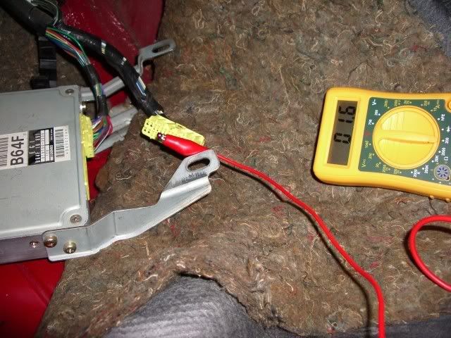
ok so as you can see the multimeter confirms that we have the correct wire identified at the ecu.
then we need to find the black earth wire and the red / white 12v wire. again, checking with the multimeter to confirm
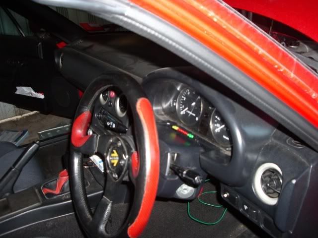
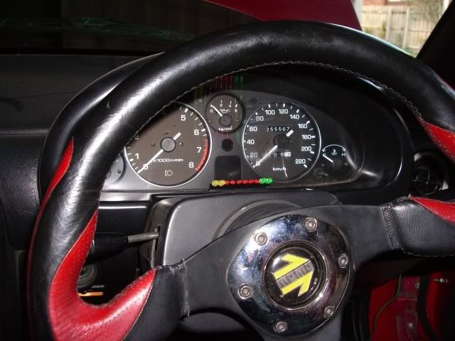
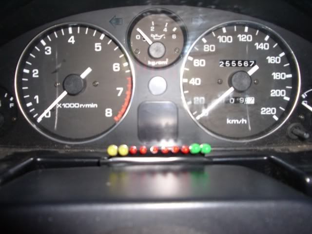
next up is to slot the meter into position to see how it looks. i chose to mount it in the little space between the steering column and the instrument cluster. i thought this was a nice inconspicuous spot, as well as being right in the line of sight. as you can see, i have packed the board with some foam and wrapped it in black tape so it will blend in to it's surroundings.
i fastenned it in place using some adhesive velcro strips, so i can remove it again if i choose to with minimum fuss. here's some shots from a few different angles
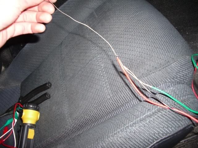
getting the wires from the drivers side thru to the passenger side (where the ecu is) proved to be difficult as it's a really tight fit under the dash. not much room at all. so i solderred all the wires on to a stiff, solid peice of wire and shoved it thru, then pulled it out the other side.
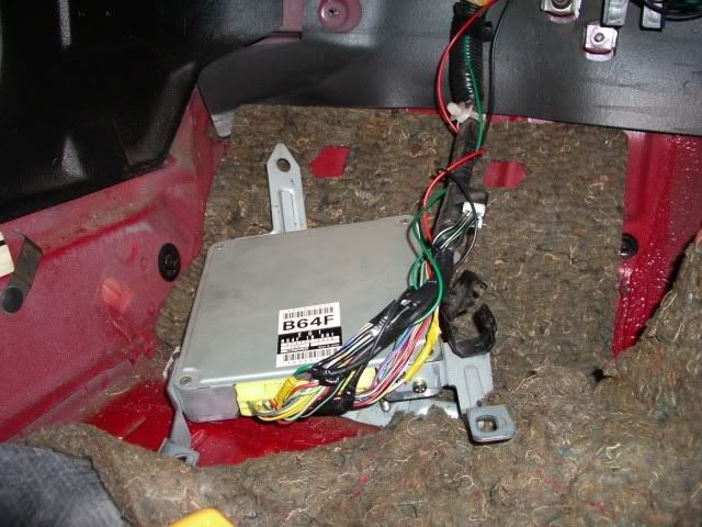
then you just splice the wires in at the right spot, and voila, all done.
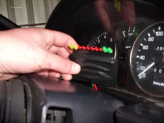
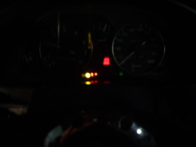
so here it is , you can't tell from this shot but this is the meter indicating that we're in closed loop mode. the meter is oscillating up and down, \"knight rider\" style
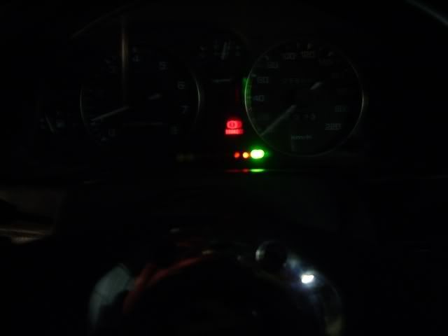
and then you plant the throttle and things get rich
so there ya go. just thought i'd share this with you guys as i'm on broadband now so figured i'd take advantage of it and post lots of photos
i'm looking forward to driving the car wiith this meter in it just to get an understanding of what is going on with the air/fuel mixtures at different loads. it should help me down the track when i install the DFA etc.
so i have been fiddling with this jaycar digital fuel adjuster (DFA) that i bought a few weeks ago. it's all finished and working perfectly on the test bench. this is a picture of the test / calibration rig. you can see the hand controller there in the picture as well, anyway it's all working as it should be
so before i install it in the car, i realised that unless i had some way to see what it was doing then it would be a waste of time. so i figured i'd need some way of monitoring the air/fuel mixture, via the O2 sensor, to see what affect any adjustments i make wiith the DFA are having. so of course my first port of call is to jaycar to see what kits they have. it turns out they have about 5 or 6 kits that all seem to do the same thing
i settled on the \"car fuel mixture display\" kit number KC5195, for $14.95, and here is the end result
you'll notice that the red leds in the middle are 3mm leds while the yellow and green leds either side are 5mm leds. the kit comes with 5mm leds all round, using green ones in the middle and red ones at the lean end of the scale, and yellow at the rich end. i decided to set it up differently as i found the red leds aren't as bright as the yellow and green ones, so figured these would be best in the \"normal\" range rather than at the extreme of the scale. i aslo chose to use smaller leds in the red range, purely coz i thought it would look better / less instrusive.
ok so now the fun starts, we move on to fitting it in to the car. using the wiring diagram posted by a friendly forum member, we know that the O2 sensor wire is the red / blue wire on the ecu. just to be sure, i thought it was a good idea to double check this by shoving a pin thru the O2 sensor wire in the engine bay, and checking that it shows up at the ecu where it is supposed to
ok so as you can see the multimeter confirms that we have the correct wire identified at the ecu.
then we need to find the black earth wire and the red / white 12v wire. again, checking with the multimeter to confirm
next up is to slot the meter into position to see how it looks. i chose to mount it in the little space between the steering column and the instrument cluster. i thought this was a nice inconspicuous spot, as well as being right in the line of sight. as you can see, i have packed the board with some foam and wrapped it in black tape so it will blend in to it's surroundings.
i fastenned it in place using some adhesive velcro strips, so i can remove it again if i choose to with minimum fuss. here's some shots from a few different angles
getting the wires from the drivers side thru to the passenger side (where the ecu is) proved to be difficult as it's a really tight fit under the dash. not much room at all. so i solderred all the wires on to a stiff, solid peice of wire and shoved it thru, then pulled it out the other side.
then you just splice the wires in at the right spot, and voila, all done.
so here it is , you can't tell from this shot but this is the meter indicating that we're in closed loop mode. the meter is oscillating up and down, \"knight rider\" style
and then you plant the throttle and things get rich
so there ya go. just thought i'd share this with you guys as i'm on broadband now so figured i'd take advantage of it and post lots of photos
i'm looking forward to driving the car wiith this meter in it just to get an understanding of what is going on with the air/fuel mixtures at different loads. it should help me down the track when i install the DFA etc.

