Lokiel's "Gina" (2004 Titanium SE)

Chat to do with your MX5/Miata/Eunos Garage Ride(s).

Moderators: timk, Stu, zombie, Andrew, The American, Lokiel, -alex, miata, StanTheMan, greenMachine, ManiacLachy, Daffy

Nevyn72
Speed Racer
Posts: 2180
Joined: Fri Nov 29, 2013 8:51 am
Vehicle: ND - RF
Location: Sydney

Re: Lokiel's "Gina" (2004 Titanium SE)

Postby Nevyn72 » Sun Jul 11, 2021 12:40 pm

Lokiel wrote:Hopefully will get time tomorrow to post some of the other stuff I've been doing...


Yay! :mrgreen:
"A Convertible has a top you can put down when the weather's nice...... A Roadster has a top you can put up when the weather's bad."

User avatar
greenMachine
Forum Guru
Posts: 3945
Joined: Thu Apr 24, 2003 11:00 am
Vehicle: NB SE
Location: Sports car paradise - Canberra
Contact:

Re: Lokiel's "Gina" (2004 Titanium SE)

Postby greenMachine » Sun Jul 11, 2021 1:37 pm

That is a great write up Lokiel, well done and much appreciated.

Blimey, those seats are expensive :shock: , AND you bought a pair :shock: :shock: , AND you paid duty :shock: :shock: :shock: . DT website quoted (IIRC) $1246, presumably since they knew I was in Oz they quoted a price less VAT - OTOH it would be a pleasant surprise to get a 20% discount, but still a grand each, before all the extras.

While they say that their seats suit road and race cars, no certification standards are quoted for that one, is there anything in your paperwork to say FIA or TUV or some such certification? Would a lack of certification be an issue for your mod plate? It certainly could be a problem at a track.

:mrgreen:
I never met a horsepower I didn't like (thanks bwob)

Build thread

NB SE - gone to the dark side (and loving it 8) )

User avatar
Lokiel
Forum legend
Posts: 4126
Joined: Thu May 28, 2009 2:39 pm
Vehicle: NB SE
Location: Brisbania

Re: Lokiel's "Gina" (2004 Titanium SE)

Postby Lokiel » Sun Jul 11, 2021 7:06 pm

greenMachine wrote::
While they say that their seats suit road and race cars, no certification standards are quoted for that one, is there anything in your paperwork to say FIA or TUV or some such certification? Would a lack of certification be an issue for your mod plate? It certainly could be a problem at a track.
:mrgreen:

Damnit, I went back to chase this up after you mentioned it and can't see it anywhere on their site.
I thought I'd read that they were valid but may have been looking at other seats at the time.
I'll need to chase this up since it's one of the visible modz and I planned on getting the mod-plate mounted on the door sill so that I don't need to pop the hood (there's no room on the firewall anyway since that's where the roll bar mod-plate is).
Don't worry about dying, worry about not living!
Garage Thread: http://www.mx5cartalk.com/forum/viewtopic.php?f=57&t=76716

The American
Forum Guru
Posts: 1509
Joined: Fri Jun 29, 2012 9:23 pm
Vehicle: NB8B - Turbo
Location: Brisbane, Qld. Previously Perth WA
Contact:

Re: Lokiel's "Gina" (2004 Titanium SE)

Postby The American » Sun Jul 11, 2021 7:21 pm

Hats off to you Lokiel. I always enjoy reading your thought process, and the reader is always left with a very good picture of what’s required to make a modification work.

Really good technical and procedural writing.

User avatar
greenMachine
Forum Guru
Posts: 3945
Joined: Thu Apr 24, 2003 11:00 am
Vehicle: NB SE
Location: Sports car paradise - Canberra
Contact:

Re: Lokiel's "Gina" (2004 Titanium SE)

Postby greenMachine » Sun Jul 11, 2021 7:32 pm

Lokiel wrote:
greenMachine wrote::
While they say that their seats suit road and race cars, no certification standards are quoted for that one, is there anything in your paperwork to say FIA or TUV or some such certification? Would a lack of certification be an issue for your mod plate? It certainly could be a problem at a track.
:mrgreen:

Damnit, I went back to chase this up after you mentioned it and can't see it anywhere on their site.
I thought I'd read that they were valid but may have been looking at other seats at the time.
I'll need to chase this up since it's one of the visible modz and I planned on getting the mod-plate mounted on the door sill so that I don't need to pop the hood (there's no room on the firewall anyway since that's where the roll bar mod-plate is).


Is one of the seats out of the car? Have a good look at the outsides and back of the seatback, there might be a label or stamp, or it might be moulded into the GRP.

:mrgreen:
I never met a horsepower I didn't like (thanks bwob)

Build thread

NB SE - gone to the dark side (and loving it 8) )

User avatar
bruce
Speed Racer
Posts: 7662
Joined: Fri Apr 25, 2003 11:00 am
Vehicle: NA8 - Turbo
Location: Victoria
Contact:

Re: Lokiel's "Gina" (2004 Titanium SE)

Postby bruce » Sun Jul 11, 2021 7:50 pm

Worst case, email them.

User avatar
Daffy
Forum legend
Posts: 1366
Joined: Tue Apr 28, 2015 3:23 pm
Vehicle: NB SE
Location: Southern Gold Coast QLD

Re: Lokiel's "Gina" (2004 Titanium SE)

Postby Daffy » Thu Jul 22, 2021 6:20 am

The American wrote:Hats off to you Lokiel. I always enjoy reading your thought process, and the reader is always left with a very good picture of what’s required to make a modification work.

Really good technical and procedural writing.

Ditto with The American :beer: :DIY:
StanTheMan wrote:sweet, Its not all about huge hp.

viewtopic.php?t=73496

User avatar
Lokiel
Forum legend
Posts: 4126
Joined: Thu May 28, 2009 2:39 pm
Vehicle: NB SE
Location: Brisbania

Re: Lokiel's "Gina" (2004 Titanium SE)

Postby Lokiel » Fri Jul 23, 2021 10:08 pm

The Android 10.0 version of my Joying Head Unit popped up in an eBay e-mail and since mine was Android 5.0 I figured I'd update the unit because 10 is twice as good as 5!

Joying Single-DIN Head Unit:
Image

Original mounted solution:
Image
I initially used black silicon hose to fill in the gaps around the screen.

This was my original DIY headunit mount which I thought I could improve upon:
Image

The Joying Head Unit comes with a single-DIN mounting cage which is useless because it's not substantial enough to mount in a Double-DIN cavity and the front lip is designed to latch over the console fascia - when the screen is slotted into the head unit, it protrudes forward several centimetres.
I bought a generic Double-DIN cage which helped to guarantee that the Head Unit would in fact be squared correctly within the Double-DIN cavity (my previous DIY solution wasn't so took a lot of adjustments to get the alignment close to correct) and found that I could slide the Single-DIN Head Unit inside but would need to drill mounting holes into the sides of the cage to hole it (Yucko, this still involved angles but at least it's only one angle!).
Image
Image

The Double-DIN cage fits in the OEM cavity but is a few mm short.
Its front tabs latch over the OEM console on the bottom and 2x sides and barely touch the top so I decided to add a U-bracket to the rear of it and bolt it to the rear OEM bracket's oval M10 hole so that it holds firmly in place. I used an M10 bolt and nut to hold the bolt in place and another nut on top of that to bolt the cage in place.
I also had to cut some of the OEM fascia to allow the Head Unit mounting screws to slide through:
Image
FYI: When I installed the Head Unit the first time, I did it in place, in the car, which was a pain in the arse so I bought a 2nd hand console to make life easier in future for this type of work.
This console is quite daggy but great for my DIY needs.

I'd run out of 2mm thick aluminium and Bunnings only had 1mm or 3mm thick stock so I made 2 brackets from the 1mm aluminium (3mm tends to snap when bent 90* unless you take your time and heat it up) and pop-riveted them together to the Double-DIN cage:
Image
Image
Image
Image
Image
In the 3rd picture, the screen is actually upside-down. You can see that the mounting tabs can be adjusted vertically.
I mounted the screen so that it would sit as high as possible so that I could get underneath the Head Unit and bolt it in place.
I ended up using one nylon "screw" on each side since they were flatter than the screws I was using and made sliding it in and out of the OEM cavity easier.
The Head Unit is recessed far enough in the cage that when the screen is locked in place it sits flushly against the cage.

Inserted into console:
Image
You can see in the above photo how the cage's front tabs latch over the OEM fascia bottom and sides and hold it in place but barely tough the top.
I haven't bothered to push out the cage's tabs to help hold it in place because with the rear nut added to the brace, it's held firmly in place.
To add the rear nut I needed a socket extender and magnetic socket nut retainer - you NEED this, or blue-tak, otherwise you end up swearing a lot when it keeps falling out of the socket as you get close to screwing it on.
Image

Mounted without and with the OEM console bezel:
Image
Image
- the OEM console bezel originally had a glued-on chrome fascia - removing the glue scuffed the crap out of it

I have a 3D printer now so decided to make my own Head Unit bezel to fill in the gaps.
My initial version was just to get it sized correctly and I have lots of orange PETG filament.
Image

The first thing I noticed was that the bottom jutted out quite a bit, mostly due to it touching the cage's front tabs/latches.
I also had to figure out how to lock the bezel in place.
The screen has 3 small screws on the top and bottom and 2 small screws on each side
Unfortunately the screws are too shallow to screw through my DIY Head Unit fascia and into the screen housing so I'd have to wedge it into place.

I updated my 3D model to make it shallower at the bottom, added small spheres that would "lock" into the screw centres and a small wedge on top to firmly push the top down:
Image
- the 1st and 3rd sphere's on the top were removed because they bowed the top too much.

It now sits very tight and requires paper clips to be removed so it's not going to fall out easily:
Image
Image

... more to come this weekend!
Don't worry about dying, worry about not living!
Garage Thread: http://www.mx5cartalk.com/forum/viewtopic.php?f=57&t=76716

User avatar
PaulF
Racing Driver
Posts: 1801
Joined: Fri Jan 28, 2011 5:55 pm
Vehicle: NA6
Location: Newcastle, NSW

Re: Lokiel's "Gina" (2004 Titanium SE)

Postby PaulF » Mon Jul 26, 2021 9:43 am

Nice heads-up on the single DIN unit. I usually avoid unknown Chinese stuff but if you liked the first one enough to buy the new model, that seems like a pretty good endorsement.

User avatar
Lokiel
Forum legend
Posts: 4126
Joined: Thu May 28, 2009 2:39 pm
Vehicle: NB SE
Location: Brisbania

Re: Lokiel's "Gina" (2004 Titanium SE)

Postby Lokiel » Wed Aug 11, 2021 10:27 pm

Last weekend's efforts:

I've been focusing on implementing the next generation of my DIY sensor box and needed to wire-up two temperature sensors to measure temperature inside and outside my airbox since I want to find out how effective it is and whether I need to add additional insulation to it.
To do this I needed to route the wiring from the sensor box to the airbox.

There's a grommet on the hot-side firewall to route wiring into the passenger footwell:
Image

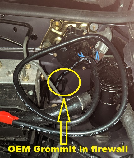
I'd used this before when I was using the Adaptronic ECU and it was a pain in the arse trying to thread individual wires since you also need to get past the footwell's insulation layer.
It was much easier using a sheathed cable with multiple wires.

Sequential (vs OEM wasted-spark) firing of the coils has always been a goal of mine which requires 2x additional wires to the ECU that control SparkC and SparkD so I figured I'd use a 6-core cable, 2x each for the two temperature sensors and 2x for the igniters.
There is no way that I'd be able to thread the 2x igniter wires separately later.

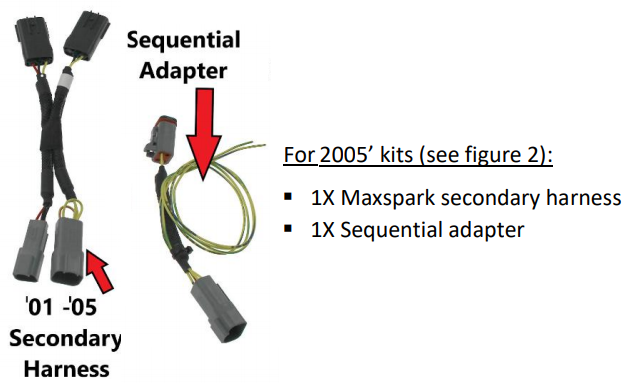
I received an e-mail from DIYAUTOTUNE regarding their new MaxSpark product which included everything needed to install an aftermarket CNPS using wasted-spark or sequential firing, including coils, mounting bracket and harnesses, as well as configuration details for the MS2/3 regarding the coils.
The coils are new AMP EFI IGN-1A coils, not 2nd-hand GM or Toyota coils and DIYAUTOTUNE have worked with them to define the correct settings which is a good thing (the GM and Toyota settings have largely been deduced by users).
https://www.diyautotune.com/product-releases-updates/max-spark-the-ultimate-miata-ignition-upgrade/
Image
Image

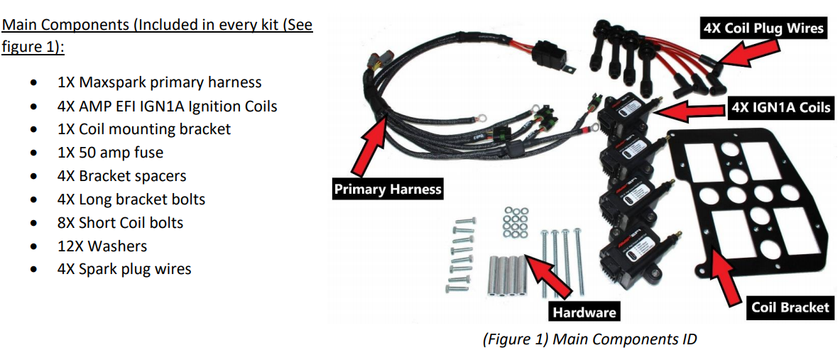
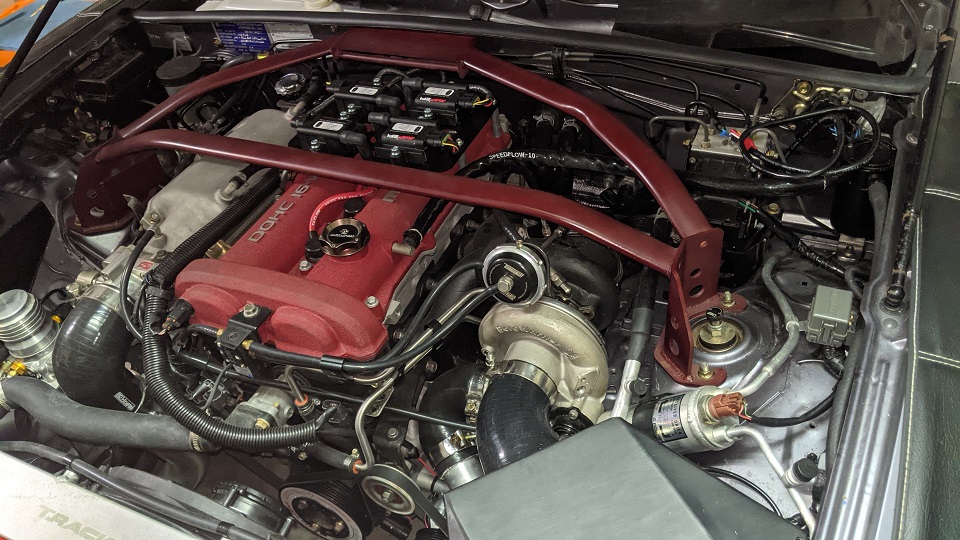
My biggest concern was "would it allow me to retain my 3-point Carbing front strut brace"?
I love it since I use it to mount a brake master-cylinder brace and it's handy to lean on when working in the engine bay - plus it looks great IMO!
Looking at the photos on the site made me think it would fit OK so I bought the kit since making harnesses for the coils is time consuming and you need to do it properly, you can't afford to have any shorts or wires detaching from their pins.

My first attempt at a wasted-spark harness was a bit dodgy and my 2nd attempt was over-engineered, I should have used a smaller wire gauge which made fitting them to the coil plugs harder than it should have been - it's strong as hell though, none of those wires will ever pull out.
Image
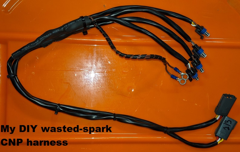
It's quite long which allowed me to tuck it away out of site where I wanted; the first harness was shorter which meant I could only stuff the wiring behind the motor.

I really didn't want to make a new harness and prefer to keep my existing harness for a wasted-spark setup since I know it works.


Thankfully all bolts supplied are metric - I didn't use any of them though!

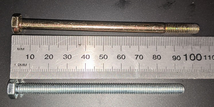
The first thing I noted was that the long bolts used to attach the mounting plate to the rocker cover were a little too short for my liking, when bolted in fully I could feel from underneath that they were at least one thread short and those bolts should only be lightly torqued (~55 In/lbs).
I bought some longer bolts from Bunnings Motorsport that are 5mm longer and these protrude from underneath by about 2mm:
Image

The short bolts for mounting the coils to the mounting plate are way too long so I used some short Allen bolts instead (which still needed some trimming because adding lightness is important).

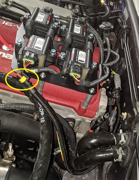
With this kit, before bolting on the mounting plate, you MUST first thread all the ignition wires through the mount plate, connect them to the coils and plug in the rear two ignition wires - you CANNOT do it later. The instructions do make this clear though so I had to smack myself in the back of head for making this mistake initially.
My DIY solution made it hard to disconnect the plugs from the coils, I needed a long flat screwdriver to unclip them before sliding them off, but the MaxSpark kit is MUCH harder to change components, you need to unbolt the mounting plate.

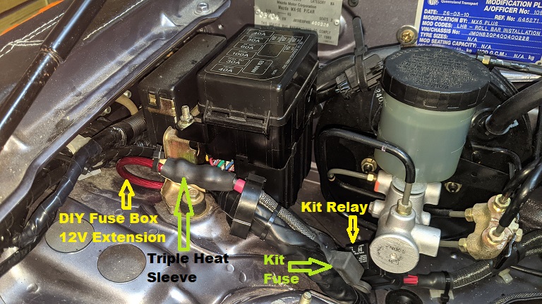
The MaxSpark kit harness requires an additonal 12V source and includes an in-built fuse and relay.
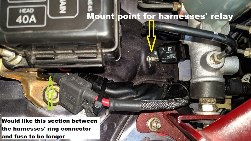
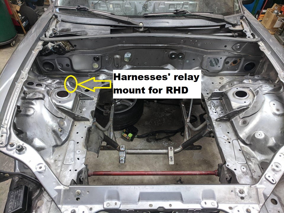
The documentation says to mount the relay on the coldside firewall but we RHDs have no room there.
Luckily there's an OEM 6mm threaded hole on a 45* slope on the coldside suspension mound (directly below the from of the brake master cylinder) so I used that - you don't want to mount relays horizontally on the shelf because water may pool up around them).

The additional 12V source was the biggest hurdle.
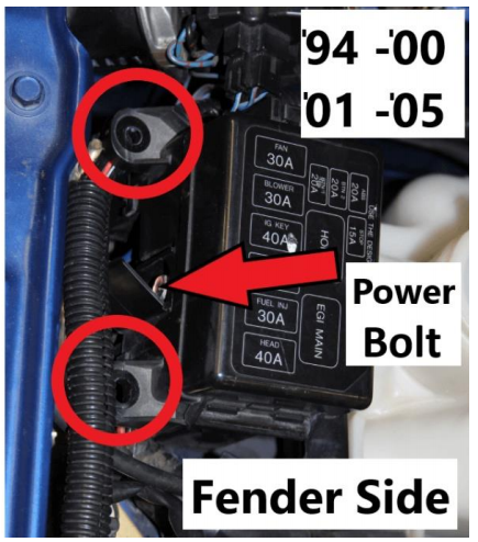
The instructions recommended the following for my model:
Image
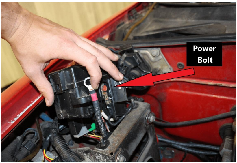
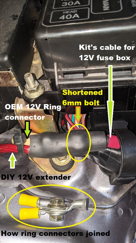
The OEM ring connector to this bolt (yes, even mine has red paint on it) has 2x wires attached, one being quite thick.
The instructions indicate that there is a "door" to access this bolt.
On my car, this isn't the case, the top of the fusebox unclips and can be pulled off in one piece - there is no door access to that bolt.
The OEM wiring to the bolt is from directly underneath and there is no room to include it and the new 12V massive cable of the new harness to it!

I had to make a cable extension from that bolt, outside of the fuse box and joined the existing OEM 12V wiring and new harness 12V wire to it using ring connectors, a shortened M6 nut and bolt and 3x layers of heat-shrink:
Image
Image

The instructions recommend ground points for the harness:
Image
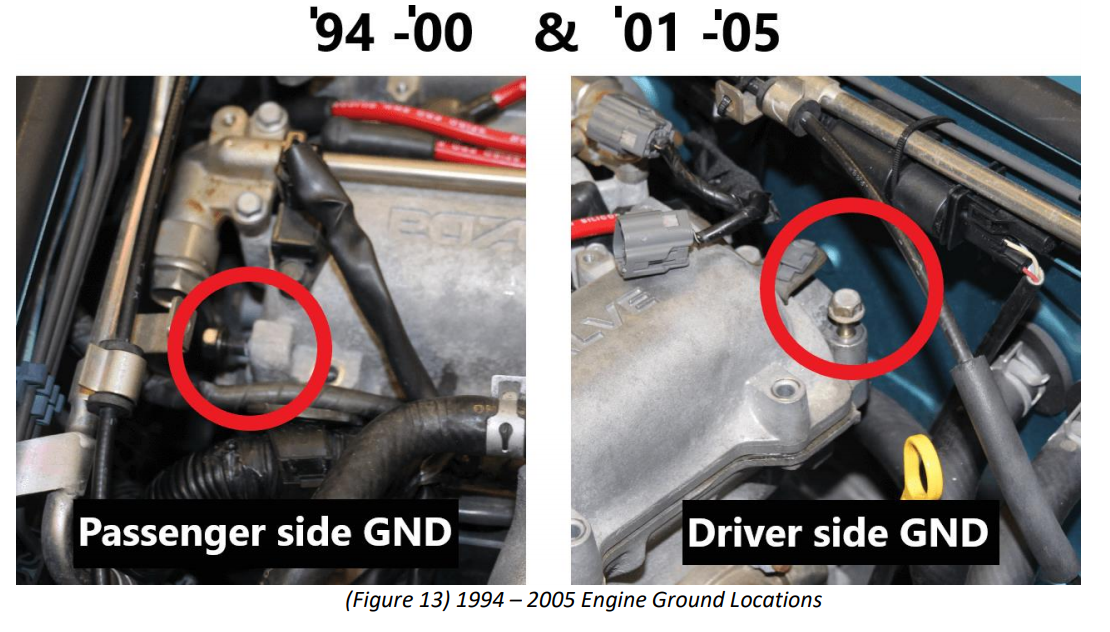
For my original DIY wasted spark implementation I used the '94-'00 ground point on my MSM and it was still more convenient to use it so I used that instead of the '01-'05 recommendation. I know it works and can switch it over easily enough if needed.

The extra wiring is all zip-tied behind the engine, not as slick as before though :(
Image
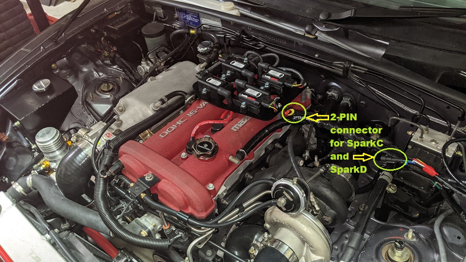
The circled yellow plug is the 2-pin SparkC and SparkD connector for the MS3.

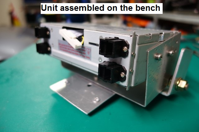
Here's what it looks like so far:
Image
Image
Image

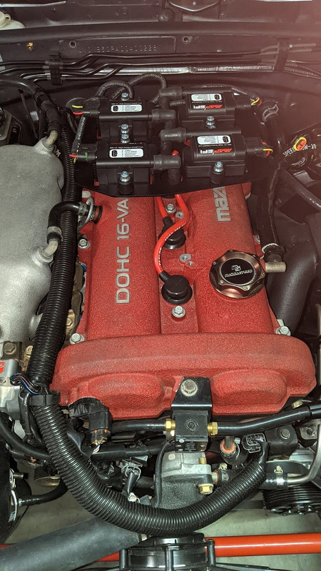
I still need to wire up the MS3 to see if it all works - if it doesn't, I can easily revert to the previous wasted-spark solution.

... and I'd forgotten about the 2x temperature sensors. One will be mounted inside the cold air box, the other just outside of it. They cannot be mounted to the same point/bracket since it may affect the readings.
Don't worry about dying, worry about not living!
Garage Thread: http://www.mx5cartalk.com/forum/viewtopic.php?f=57&t=76716

User avatar
Lokiel
Forum legend
Posts: 4126
Joined: Thu May 28, 2009 2:39 pm
Vehicle: NB SE
Location: Brisbania

Re: Lokiel's "Gina" (2004 Titanium SE)

Postby Lokiel » Thu Aug 12, 2021 12:50 am

MT.net now has info on this kit in a couple of threads and I noticed the following picture:
Image

The ^&%%*& Power Bolt they recommend for my model is on the Fender Side ^(*&^$&&%^$(*

... and it DOES have door access to the %%&%*&^%% 12V Bolt &&*)*)*((*
... and it's painted red too!

Not sure if the instructions have been updated since I installed mine or I simply used the wrong reference picture but this would have saved me at least 2x hours since I needed a trip to AutoBarn.

Electrically both bolts are connected so either could be used but, being anal, I 've just switched to using the recommend 12V fuse box source since it eliminated the short 12V extender cable I added.

It took a LONG time to cut through the triple heat shrink so I have no doubts that it would have held up to the task.

The little door over the bolt will NOT close with the 2x ring clips attached, the cables are too thick.
I bolted everything back up and the OEM bracket helps push the door mostly closed and then taped over it to enclose/seal it.
Don't bother taping until you've done this unless you have REALLY strong electrical tape, mine wouldn't hold it closed.

It would have been nice to have a little more gap between the ring connector and the fuse on the harness because the fuse only just makes it outside the fuse box.
Don't worry about dying, worry about not living!
Garage Thread: http://www.mx5cartalk.com/forum/viewtopic.php?f=57&t=76716

The American
Forum Guru
Posts: 1509
Joined: Fri Jun 29, 2012 9:23 pm
Vehicle: NB8B - Turbo
Location: Brisbane, Qld. Previously Perth WA
Contact:

Re: Lokiel's "Gina" (2004 Titanium SE)

Postby The American » Thu Aug 12, 2021 8:05 am

It’s a neat solution to make use of the IGN-1A.

I would have preferred this over remote mounting, that’s for sure. My crank case vents as they are now interfere with this arrangement.

User avatar
Lokiel
Forum legend
Posts: 4126
Joined: Thu May 28, 2009 2:39 pm
Vehicle: NB SE
Location: Brisbania

Re: Lokiel's "Gina" (2004 Titanium SE)

Postby Lokiel » Thu Aug 12, 2021 10:18 am

Here's the new fuse box connection and close-up of the harnesses' relay:
Image
Don't worry about dying, worry about not living!
Garage Thread: http://www.mx5cartalk.com/forum/viewtopic.php?f=57&t=76716

User avatar
Lokiel
Forum legend
Posts: 4126
Joined: Thu May 28, 2009 2:39 pm
Vehicle: NB SE
Location: Brisbania

Re: Lokiel's "Gina" (2004 Titanium SE)

Postby Lokiel » Thu Aug 12, 2021 11:31 am

Image
Don't worry about dying, worry about not living!
Garage Thread: http://www.mx5cartalk.com/forum/viewtopic.php?f=57&t=76716

User avatar
bruce
Speed Racer
Posts: 7662
Joined: Fri Apr 25, 2003 11:00 am
Vehicle: NA8 - Turbo
Location: Victoria
Contact:

Re: Lokiel's "Gina" (2004 Titanium SE)

Postby bruce » Thu Aug 12, 2021 12:38 pm

Wow, taking out your motor to install some wiring is a bit extreme!


(hee hee).


Return to “MX5 Garage Chat”

Who is online

Users browsing this forum: No registered users and 5 guests