Sorry to see that this forum is dying due to lack of input from members and I'm guilty of that too so I'll try and keep my build activities up to date starting now.
I've been working on a sensor box that supports:
4x temperature sensors
2x pressure sensors
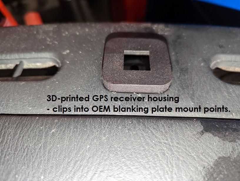
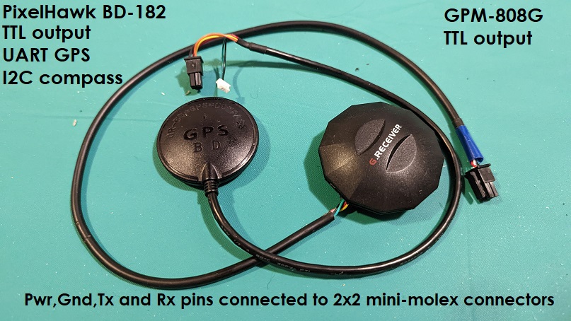
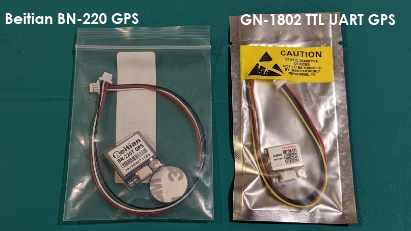
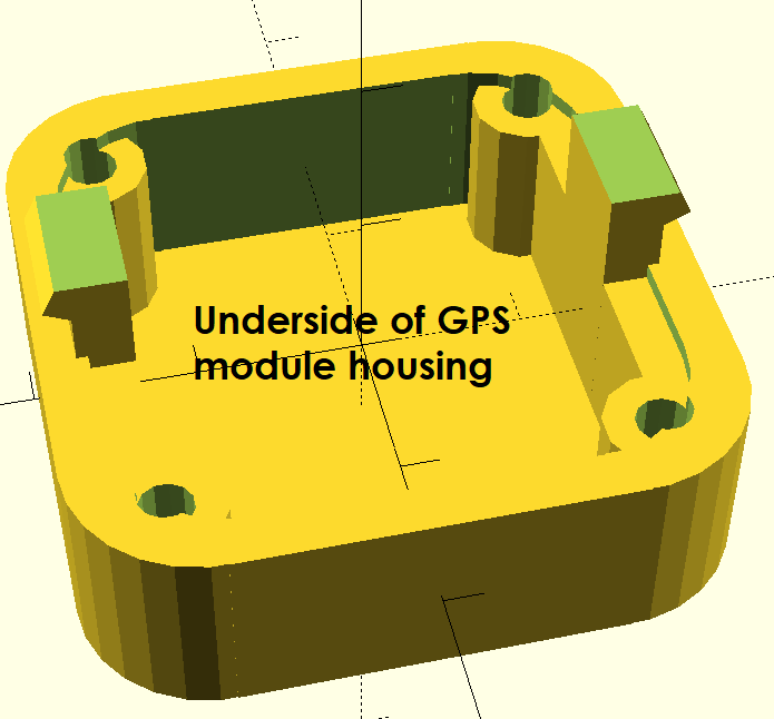
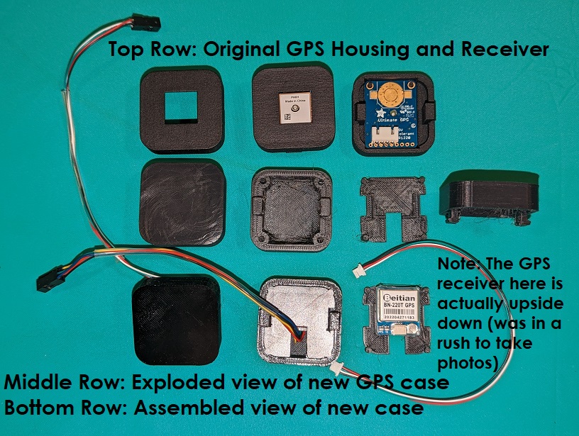
1x 10Hz GPs
1x Gyroscope
1x or 2x OLED displays that replace the edge OEM gauges to display data
3x Digital switches (one used to cycle through the OLED screens)
1x Innovate Wideband O2 sensor
1x fuel level input (needed if 2x OLEDS are used)
1x CAN bus so that data can be sent and received to/from an aftermarket ECU
The sensor box requires 34 input pins and power input.
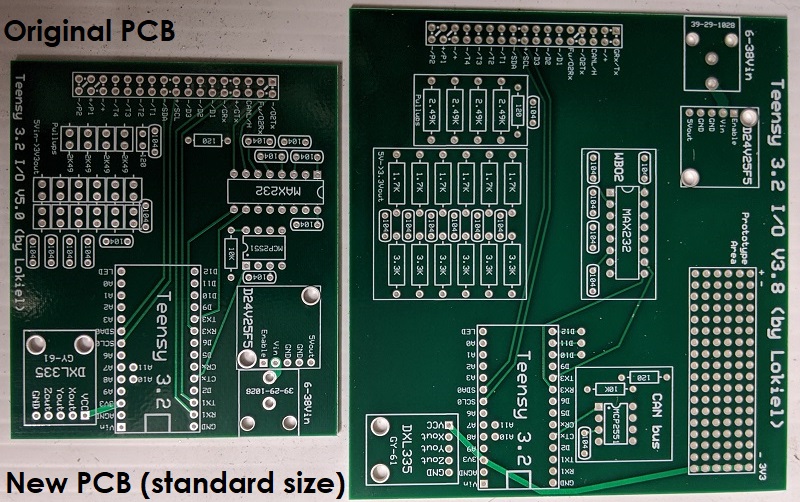
The original socket I used was small but a pain in the arse to upgrade.
If every pin was populated it wasn't too hard to install all the wiring but no-one wants to do that, you only want to install what you need as you need it.
Removing the locking mechanism proved to be problematic; even with the correct tools I practically destroyed the locking mechanism.
Something simpler was needed.
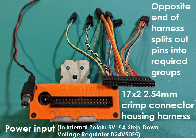
I found a picture of a Pololu harness which looked perfect for what I needed:
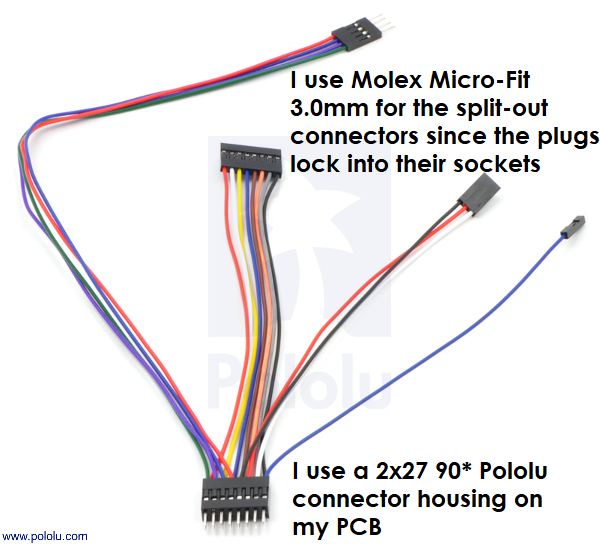
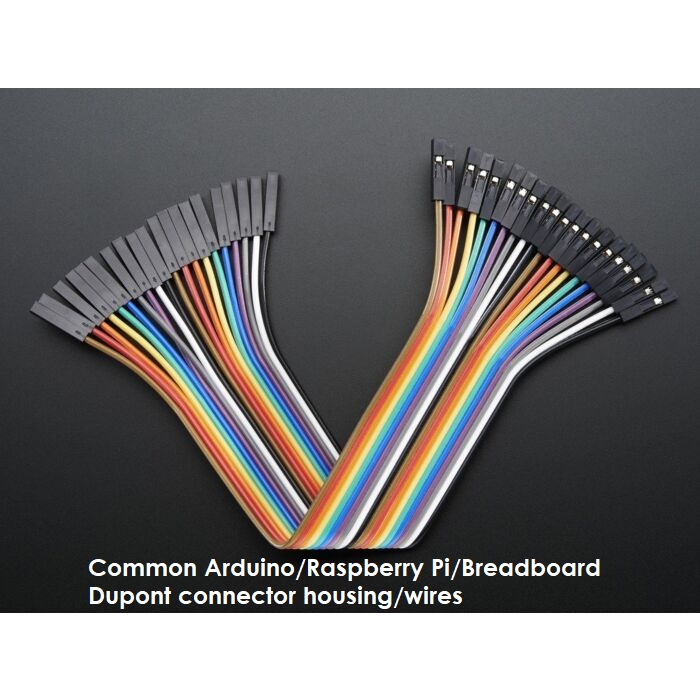
This harness uses common Dupont connecters/wiring which are used on breadboards and Arduino and Raspberry Pi projects. It's very easy to add and remove pins from these; to remove a pin you just need a needle and pull up the locking tab and the pin slides out.
The 2x27 female connector is "strong enough" to hold the connector to the PCB's 2x27 90* connector but the split-out connectors need something stronger so I use Molex Micro-Fit 3.0mm connectors.
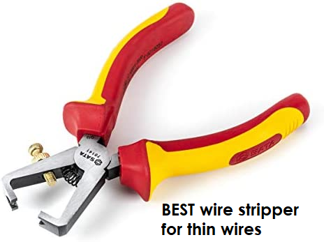
Stripping one end of the Dupont wires for the Molex pins was annoying initially because the wires are very thin and I'd often end up with only 1 or 2 wire strands so I couldn't crimp the Molex pins to them and I wouldn't trust a single wire for the electrical connection either.
After a bit of Googling I found that the following type of wire stripper works best for thin wires so I bought one - it DOES work well for small wires once you've set the screw correctly:
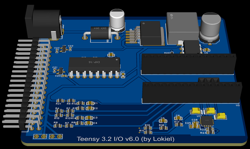
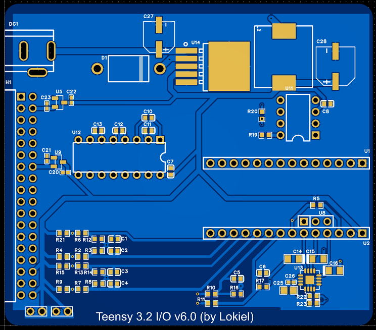
I decided to use a locking connector on the PCB just to be safe.
For a 2x27 pin PCB connector I needed to use a 2x20 pin connector socket and shorten it by one pin so that the locking connector locks down onto the 2x edge pins.
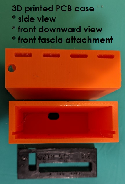
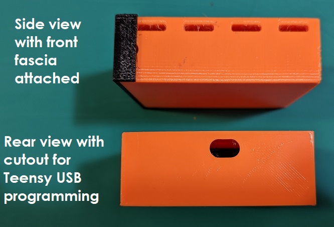
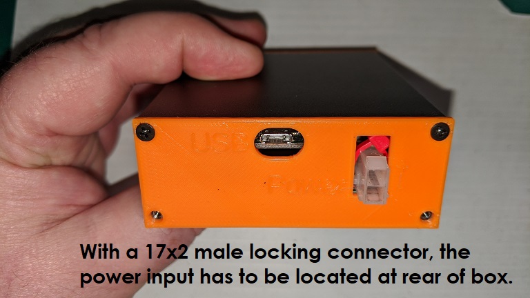
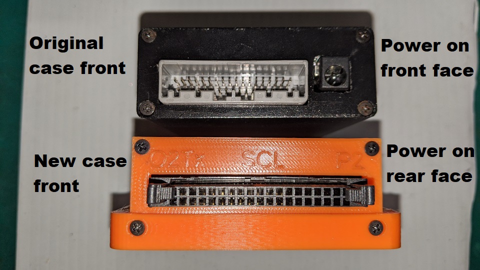
Unfortunately the locking connector takes up almost the entire fascia width so the power input needs to be mounted on the rear fascia.
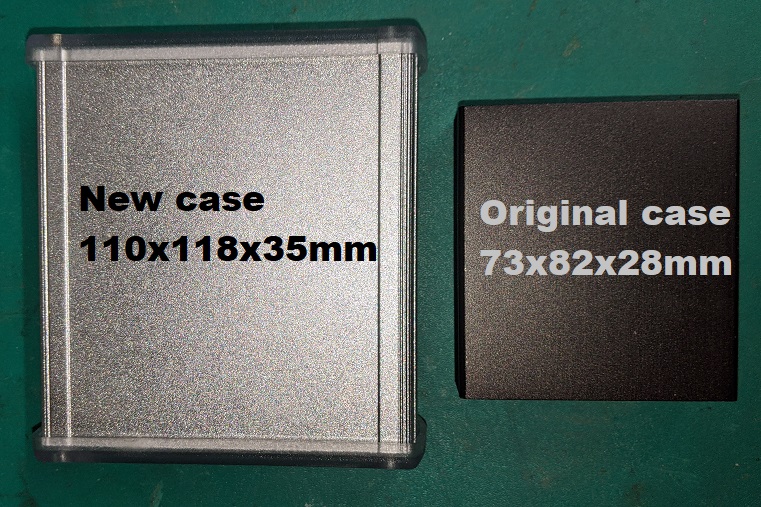
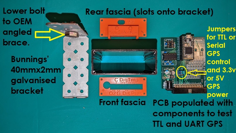
I used my 3D printer to print custom front and rear fascias for the case:
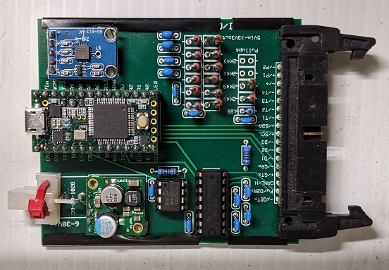
The bottom left PCB daughter board is a Pololu 24-5V converter so the box can be powered by 12V or 5V input sources and won't get too hot.
Users can choose to power the box with 12V or 5V.
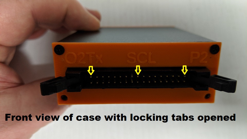
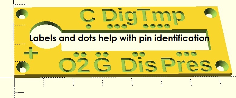
The yellow arrows point to where the printed label aligns to to make it easier when pinning the harness.
ManiacLachy has been testing my original sensor box and it has been flaky at times, noticeable because the OLED display locks up.
I haven't noticed this on my testbed or in my original car installation but he actually drives his car so is finding different errors.
One of the issues I've suspected is that I use I2C to control the OLED(s) and found out that they should only be used for short distances, < 1x metre.
This means that my sensor box needs to be located as close to the OLED(s) as possible.
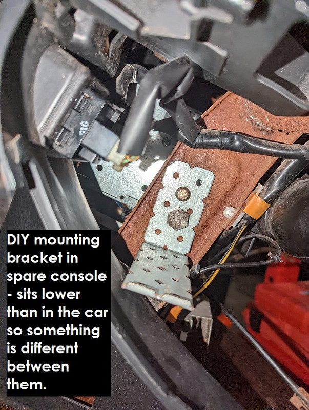
The bottom 3D printed chunk allows the case to sit inside it and has 4x vertical slots for zip-ties to allow it to be mounted to the crash bar behind the cluster.
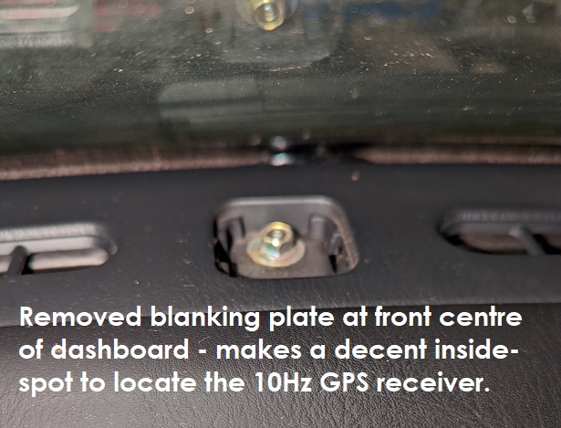
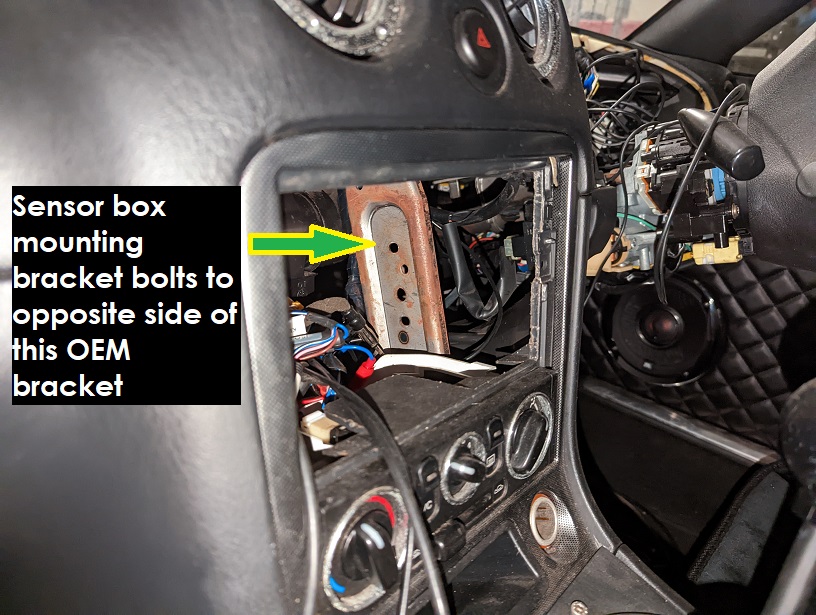
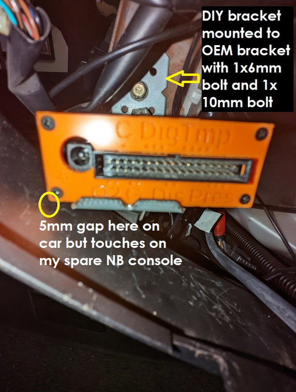
This is where I planned to mount the sensor box:
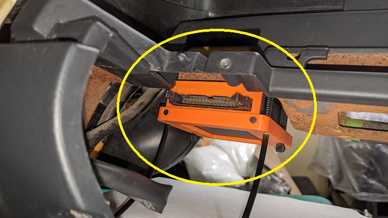
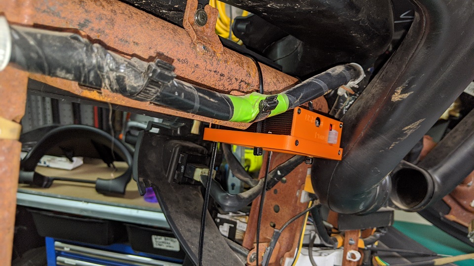
It wasn't too hard to mount this in my spare NB console that I originally bought to test-fit my Android Head Unit but fitting it in the car was a whole different story and accessing the rear power connector was going to be almost impossible!
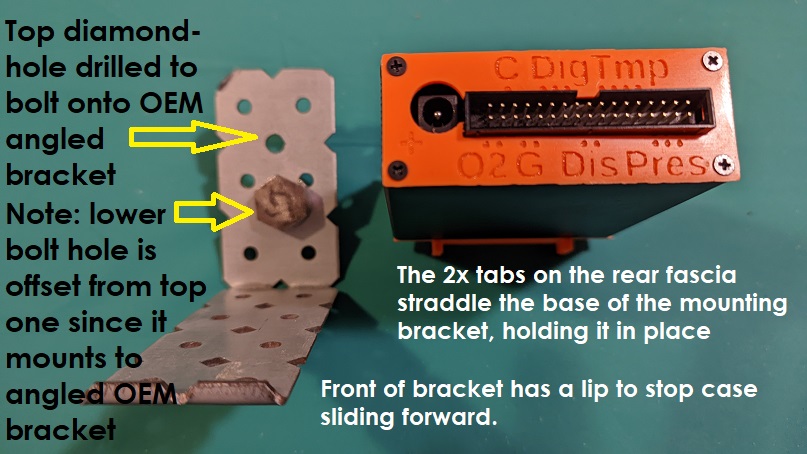
The previous photo though gave me an idea - I can actually build a bracket to mount the sensor box using that OEM strut in the bottom+middle of the photo - I'm already bolting my DIY Android Head Unit mount there, the bracket can go on the other side!